STEP ONE – HOW TO ORDER THE CORRECT SHIMS WITH YOU PUMPS
Before replacing your Deutz injection pump, there is some key information to gather in order to get the correct parts. If you have ever changed a timing belt on one of these engines you know that the injection pump timing is based on the camshaft, and it is the camshaft that drives the tappets to pressurize the injection pumps. Other than the timing belt, proper installation of the injection pumps also impacts engine timing because 1) the distance between the top of the engine block and the tappet; and 2) the lengths of individual pumps both vary. The way to adjust for these differences is by using shims of the proper thickness that, when adjusted properly, make sure that each injection pump is supplying the correct amount of fuel to each injector at the right time.
Often the shim is mistaken for a gasket, but these shims come in a variety of thicknesses and getting the right shim depends on the measurements of your new pump and the distance from the block to the tappet when fully depressed. It is not uncommon for people to order injection pumps without considering the shim, installing their new pump and then finding the engine is not running correctly because they are using the wrong shim for the new pump. The difference between the right and wrong shim can be the difference between a healthy running engine and an engine that is smoking, hard starting, or has excess fuel consumption. To get the right shim you need two pieces of information for each pump:
- The measurement from your block deck to the top of your tappet when fully compressed (more about this below); and
- Your injection pump identification information which, for 1011 series engines will vary depending on your specific 1011 engine model and for the 2011 will be on a tag on each individual pump (more about this below).
With the correct information you can order the correct pump and shim combination to save you time, money and make installation a breeze.
What To Understand Before You Start:
With one exception, before you remove your injection pumps you must lock the control rod or “rack” with the rack locking pin. These injection pumps are designed to work in unison with each other by having each pump’s actuating arm timed in the same place when properly connected to the control rod/rack. If you don’t lock the rack, you ensure that one of your injection pumps will be out of time with the others and this can impact fuel injection pump timing for one or more cylinders leading to low power, or worse over fueling which can lead to smoke, fuel dilution in the oil, excess fuel consumption, or possibly even a melted piston if bad enough.
The one exception is when you are removing injection pumps with the intention of getting shim measurements to order new pumps that you will be replacing; you can remove the pumps to do this, but you cannot re-install the old or new pumps correctly without a rack locking pin. When you reinstall the injection pump you will also need a “marking” or “alignment pin” which often comes with the injection pump. This marking-pin locks the injection pump actuating arm in a specific place prior to reinstalling the pump into the control rod and should ensure that all injection pumps are working together equally. If you don’t have these tools, Foley Engines offers them here.
How To Use the Locking Pin:
Let’s start with the rack locking pin. First you will need to remove your engine shutdown solenoid or actuator. These are located at the front of the engine bolted into the front cover with two recessed 10mm bolts. Once removed, you can see into the open port that the solenoid/actuator was removed from, view the face of the rack, and should be able to move the rack back and forth freely by hand. If you push the rack inward toward the rear of the engine, when removing your hand, the rack should spring all the way back almost instantly. If not, you might have a sticking injection pump.
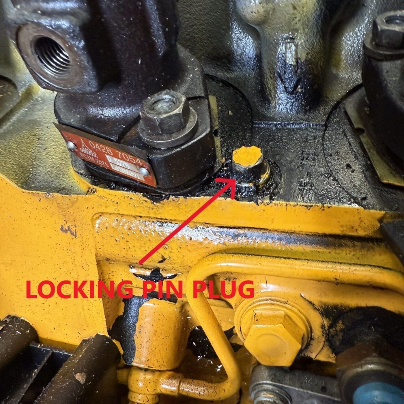
To lock the rack, you need to remove a 10mm plug from the engine block, in between the first two injection pumps (see image below). This plug will have a small crush washer that can be reused; make sure you don’t drop or lose it. Once removed, use your hand to push the rack inward until you see a circular punched hole in the rack through the open plug hole. Thread the locking pin into the hole making sure to feel for when the pin contacts the fuel rack, a little pressure on the rack is ok, it does have a little flex. Too much pressure and/or failure to align the pin to the hole can bend your fuel rack and that is a can of worms you want to avoid. Once the pin makes contact, you can move the rack inward or outward until you feel the pin drop into the hole in the rack, you might hear a click when it falls into place. Once the pin has aligned with the rack, you should not be able to move the rack much. Go ahead and thread the pin until it bottoms out. The rack is now locked into position, and it is safe to remove the first injection pump.
Measuring Shim Thickness
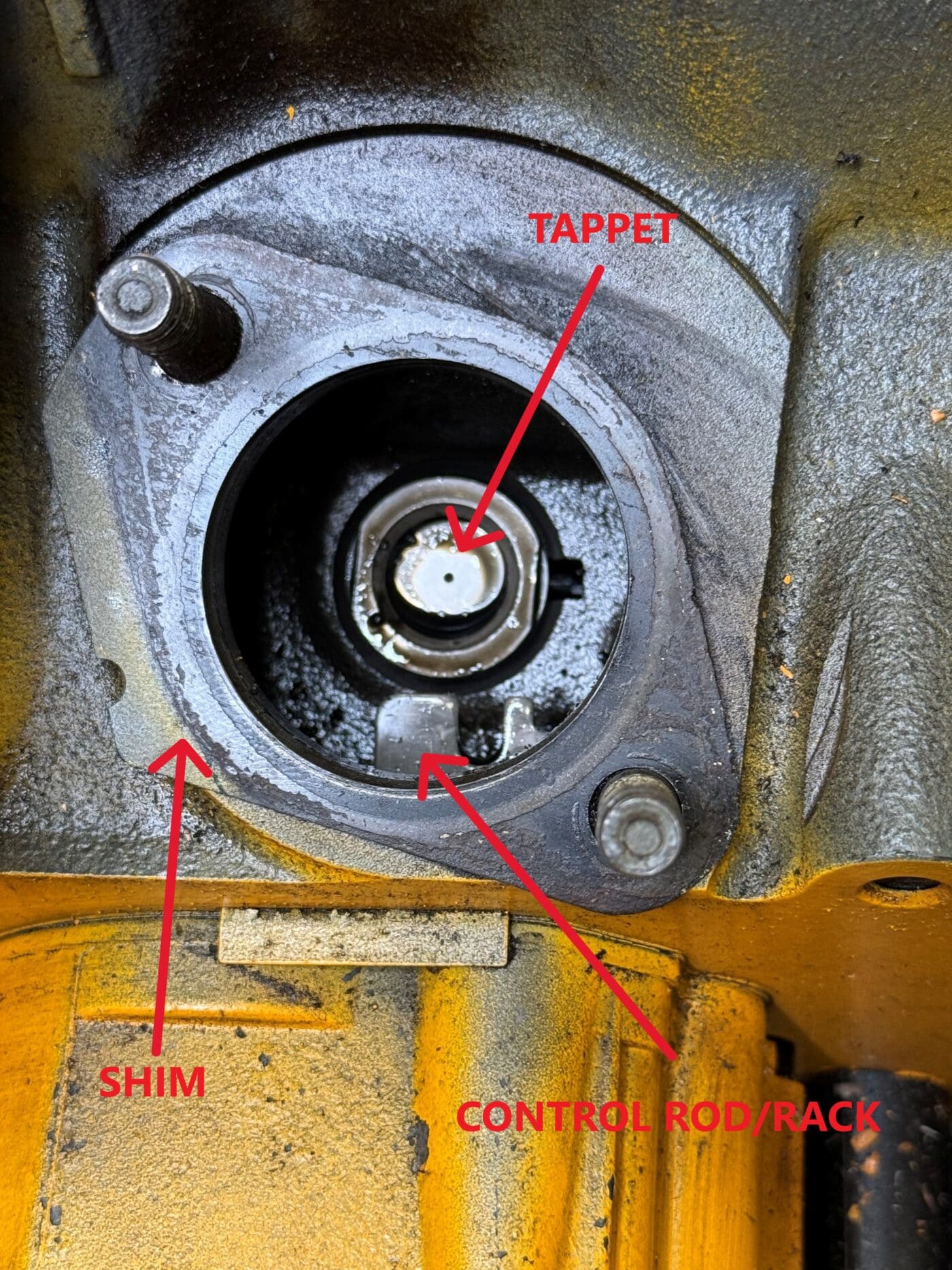
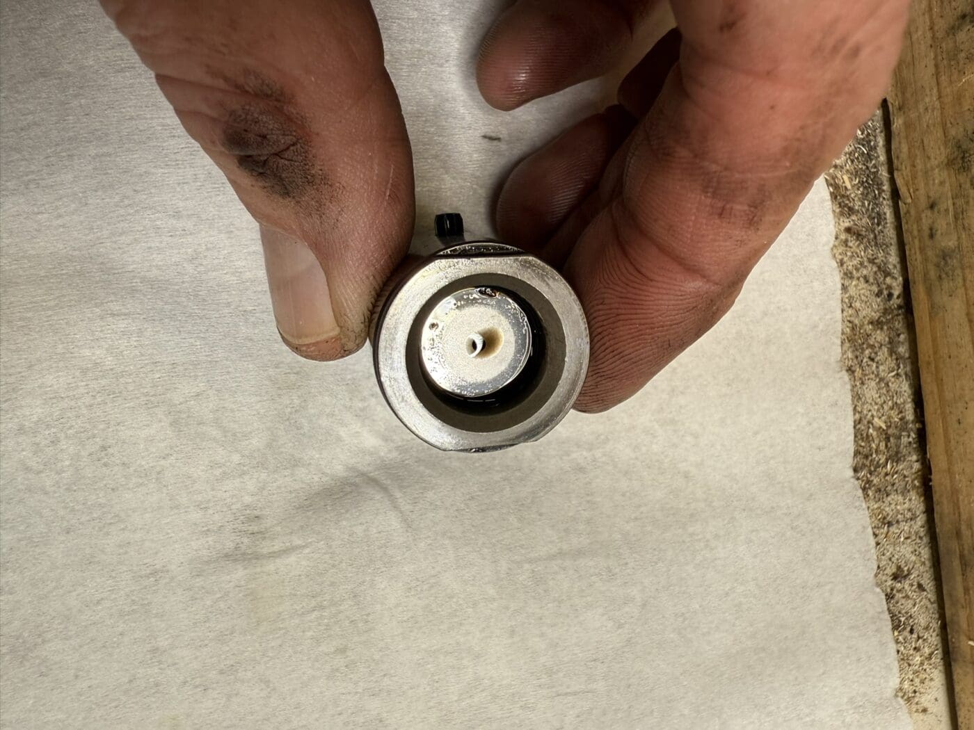
Remove the old injection pump if you have not already done so. Looking down into the port you will see the top of the tappet, using a magnet on a stick or a pair of long needle nose pliers remove the tappet from the bore. If you are doing more than one pump, make sure to keep the tappets organized so they go back in the same bore they came out of. On the 1011 engines the tappet will be one solid piece while on many 2011 engines the tappet may have a spring-loaded disc as part of the tappet where it contacts the injection pump (this was referred to as the “White Smoke Kit”, was factory installed on most of the 2011 engines, and is shown in the pictures below). If your engine has this spring-loaded disc, behind that disc will be a buildup of oil which will need to be removed to properly measure the shim thickness. This is done by compressing this disc several times until it moves up and down freely with a little pressure. Some brake cleaner or parts cleaner from your local auto parts store with a flat head screwdriver does short work of this. You will see oil release from the pin hole in the center of the disc, once oil stops coming out when compressed you should be ready to take the measurement. You will notice the hole in the picture to the right and may be able to see some oil seeping out of that hole where the depth micrometer is pressing on the tappet (this would happen if you didn’t properly remove the oil from the tappet).
- We now need to orient the camshaft to measure the depth of the bore. The camshaft needs to be at “base circle” for the injection pump lobe that serves the injection pump/cylinder you are measuring. Base circle is the lowest point the tappet can go down in the bore, this would be where the injection pump spring is the least compressed it can be once installed.
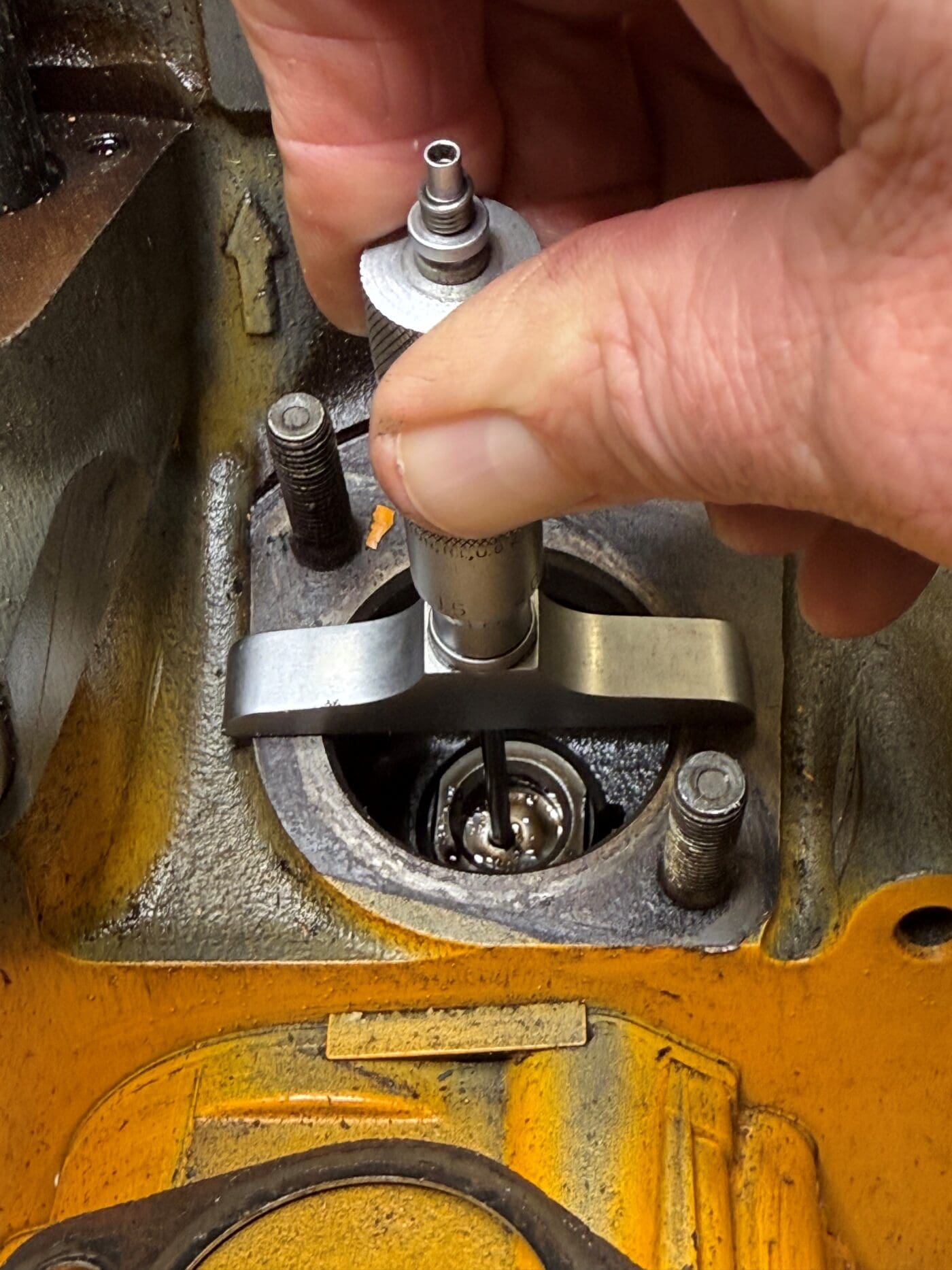
- Reinstall the tappet once the camshaft is at base circle. Using a depth micrometer, measure the distance between the face of the block and the top of the disc in the tappet when fully compressed (see picture above). You will have to use a little extra force to overcome the spring and compress the disc, but if cleared of oil, it should not take much extra force (note that, in the picture above, the tappet is not cleared of oil and you can see it coming out of the small hole in the center). You will feel the micrometer start to lift from the face of the block when the disc bottoms out. Make sure that the measurement you read is correct and the tool is seated on the block. If you don’t have a micrometer, we can recommend one for this purpose.
- Most tools in the US will use inch measurements so you will need to convert to millimeters. Take the inch measurement you get and multiply that by 25.4; for example if you measure a depth of 2.182” your conversion would be 2.182” x 25.4 or 55.4228mm. In this case, I would round it down to 55.42. This measurement can vary for each injection pump so make sure you measure each one and write down which measurement goes to which cylinder so you don’t get your measurements mixed up.
Additional Steps For 2011 Engines
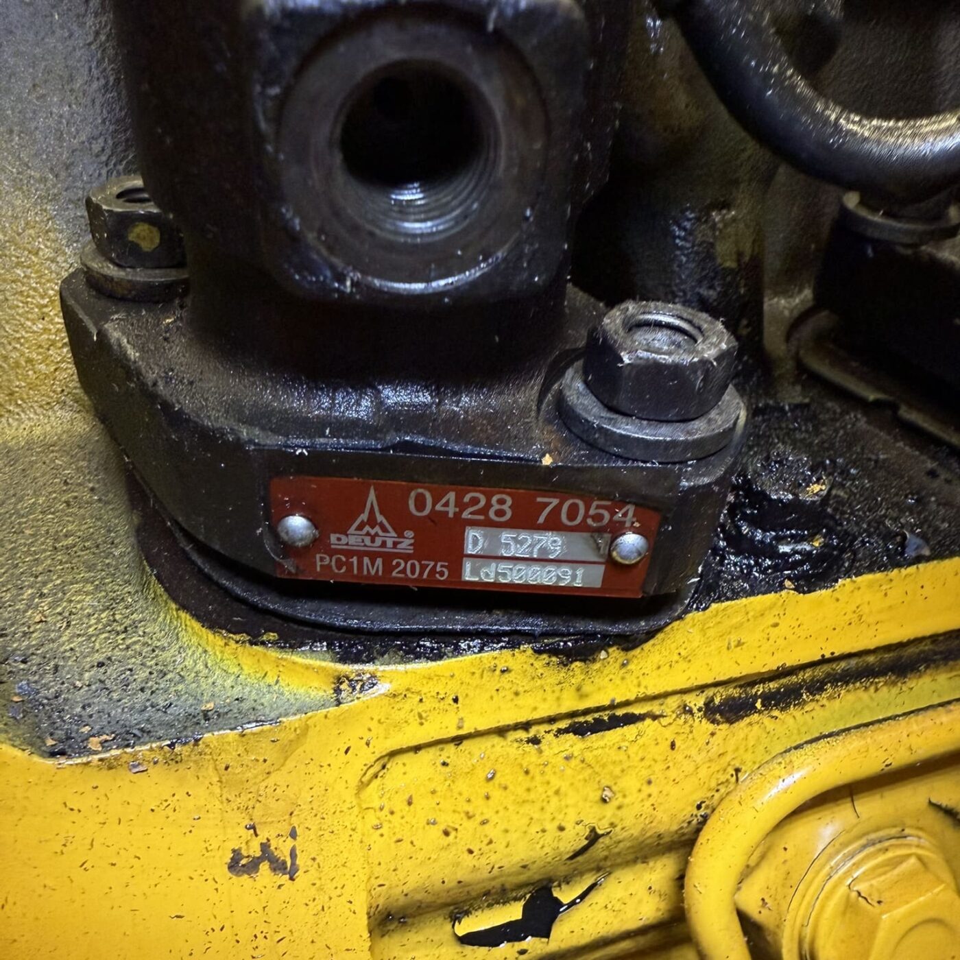
- If you have a 2011 engine, these pumps will have a specific code on a tag on the pump itself (see picture below). Your pump tag may look different than the picture below or it might be painted over and require a little elbow grease to clean off, but rest assured, the information is on that tag. On the tag will be a part number, a pump Class Code (A, B, C, or D) and a pump number code. The letter code helps us to understand which pump classes will work for your engine. The pump number code will be a combination of 4 numbers listed after the pump Class Code. An example of this could be C5527 and the numbers correspond to the measurement between the underside of the injection pump base to the bottom of the injection pump in hundredths of a millimeter (i.e. 5527 corresponds to 55.27mm). These pumps come in a variety of different pump code measurements so the pump code of your new pump will most likely differ from the pump code of your old pump and therefore it is recommended that the shim be replaced with the correct shim thickness for the new pump’s specific code. This will help to ensure that the engine timing after replacing the pump is not negatively impacted.
- Calculating the shim for the 2011 engines is very simple from here. Let’s use the examples from earlier to calculate a shim. Our measurement was 55.42mm or 5542 hundredths of a millimeter and if the new pump had a pump code number of 5592 then to find the correct shim/shim thickness we would subtract the measurement from the pump code number (i.e. 5592-5542=50 hundredths of a mm or a 0. 50mm shim). The old pump shim may be a different thickness, but for the new pump to operate correctly it needs a shim to elevate the pump from the block by 50 hundredths of a millimeter. These shims vary in size in increments of .05mm so if your calculation is not on the money, it is good practice to always round the number down, for example, if the calculated shim is 0.53mm, you would round down to a 0.50mm shim.
For 1011F Engines
- For 1011F Engines, Deutz made several different injection pumps, but all of those pumps each only had one of two different precalculated decompressed distances. The different pump decompress distances are based on the model of engine you have, for example, BF4”M”1011F or BF4”L”1011F. Aside from the “L” indicating “integrated cooling” and the “M” indicating “external cooling”, the difference in the letter changes the decompressed distance on the injection pump. For the “L” it is 58mm and for the “M” it is 59.00mm. An example of a measured depth for a F4M1011F might be 2.302” which converts to 58.47mm. Since you have a “M” engine it would have a decompressed value of 59mm so to calculate the shim thickness, you subtract your measured depth in millimeters from the M-value or 59.00- 58.47 = 0.63mm shim measurement. Again, you would round down as the shims are only available in 0.05mm increments, so your correct shim thickness would be 0.60mm.
Ordering Your Pump & Shim:
Now that you have the information you need, give us a call at 1.800.233.6539, provide your engine model number, serial number, pump Class Code, and the measurements you took and converted to millimeters. We can send you the pump and shim combinations you need.


